That Pesky dBm!

That Pesky dBm!
I love wireless (wi-fi) communications. In fact, I did my PhD around the propagation of radio waves using Maxwell’s equations. The beauty and perfection of radio waves will never leave me.
The first thing you often learn about wifi is how the frequency of the wave relates to its wavelength:
lambda=speed of light/frequency
and how dipole antennas have to be around half a wavelength long. For AM, there are long antennas (such as, with the ones that wrap copper around a core) or can be short ones (like the dipole antenna on your wireless router). Much of the magic in home networks happens around 2.4GHz and which gives a wavelength of 12.5cm, and where if you measure the dipole antenna, it will be around 6.25cm high. Once you learn about this, you are often hooked on the wonderment of radio waves. It has solid mathematics, but is also a black art (ask any RF engineer and they will tell you this)!
I, too, love all the different antenna shapes and designs and try to imagine how they spread their signals. But those pesky metal things get in the way and can bounce signals in other directions (which is sometimes a good thing, of course), and the other materials, such as concrete, will reduce the signal strength. For all the maths of Maxwell’s equations, a lot comes down to measurements and simulations.
Overall, too, wi-fi has freed us from those pesky twisted pair of cables and those troublesome RJ45 and RJ11 connectors. And, at the core of wifi, is signal strength, and where the stronger the signal, the more chance we have of creating a good network connection. For this, with most IEEE 802.11x standards, the bandwidth that you can use often relates to the signal strength that you have — so the further away you are from the transmitter, the more likely it is that you will have a lower bandwidth capacity.
At home, you might have a MIMO (Multiple In, Multiple Out) transmitter, and which bounces signals of objects and transmits on multiple channels. This might give up to 540Mbps. But, the further you go away from this, the bandwidth reduces until it will drop to nearer 11 Mbps.
And, so RSSI (Receiver Signal Strength Indicator) is an important measurement as it defines how good your signal strength is — at a point in time. This will obviously vary as you move and as other things move around you.
But, at the other end, if you have too much signal strength, you can breach health and safety regulations. Currently, this is around 100mW, and you need to have a good reason if you need higher power levels than this, as too much radio power — especially around 2.4GHz — might affect someone’s health.
Let’s talk about dBs
So, what? Well, there’s a great unit that measures RSSI, and it can cause a lot of confusion … the humble dBm. Why? Well, the dB has been causing problems ever since it was used in audio applications. First, we must outline logarithms, and where if we take the log of a multiplied by b we get:
y = log (a*b) = log(a) + log(b)
and when we divide we get:
y=log(a/b) = log(a) — log (b)
and so multiplication is converted into a log add, and division by a log subtraction.
So basically we can measure the signal gain between P1 and P2 with:
Gain= P1/P2
and where P1 and P2 are defined in Watts. When they are the same, we get a gain of unity (1). Unfortunately, when we have other amplifiers and attenuation, we would then multiply these together and so our values can become rather large or very small. An improved method uses a logarithm to the base 10, and where:
Gain(dB)= log_10(P1) — log_10(P2)
When P1 is equal to P2, we get (rather confusingly) a value of zero. And when P1 has twice the power of P2 we get:
Gain(dB)=10*log10(2P) — 10*log10(P)
and, if you know logs, this gives:
Gain(db) = 10*log10(2) = 3.01dB
>>> import math
>>> 10*math.log10(2)
3.010299956639812
and when P1 is half the power of P2, we get:
Gain(db) = 10*log10(0.5) = -3.01dB
And, so a doubling of power is a change of 3dB, and a halving of power is -3bB. Are you following this? And, so, it is now easy for us to estimate the change in power, as a quarter will be -6dB, and an eighth will be -9dB. So, a drop of 3dB is quite a lot as it is half the power.
And dBm?
In wireless networks, we often have radio powers which are much less than 1W, and typically in strengths that are measured in mW (milli-Watt), and which is one thousand’s of a Watt. With this, we often use the dBm unit, and which is the dB value relative to 1mW, and now 1mW will become 0dBm. And 0.25 mW will be:
Signal (dBm) = 10*log10(0.25) — 10*log10(1) = -6dBm
>>> 10*math.log10(0.25e-3)-10*math.log10(1e-3)
-6.020599913279625
Some examples:
Most of the time, our values will be negative, as the wireless signal spreads out as it goes — this depends on the antenna that we are using, and where a dipole antenna spreads the signal all around the antenna, while a directional antenna will focus the radio power in a given direction. And, so, if we look at this table (Figure 1), we see that Receiver A receives -69dBm from Transmitter O, and Receiver I receives -79dBm from Transmitter O. Is A nearer to O than I? Well, -69dBm is much larger in signal power that 79-dBm, so that A is likely to be nearer O (or at least with a directional path). In case, the gain we have a gain of 10 dB, and which is a times ten increase in power. And, so the signal received at A is ten times that of I. Overall, it’s likely that the communication channel for A to O will be much better than I to O.

Antennas
Before we finish let’s touch base on antennas, as the shape of our antenna will define how we focus the wireless power. With this, we measure the azimuth (the x-y plane) and the evaluation (the z plane).

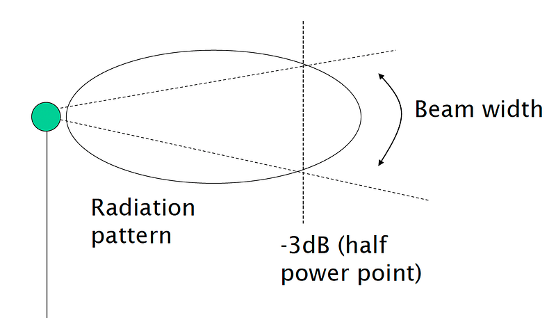
Omnidirectional antennas send their power out in every direction, while directional antennas focus the power on a defined area. The beam width is then defined as the half power — or 3dB — points of the maximum power output. A small beamwidth focuses the power, such as for point-to-point communications with a disk antenna:
An isotopic antenna is like a radiating point in space, and which will radiate its power equation in the x, y and z directions. We can then assess the isotropic gain of the antenna as the gain in power we gain for an isotropic antenna:

We define this gain as dBi. The more directional the signal, the future the signal is likely to go. Overall, a dipole antenna measures half a wavelength (6.25 cm for 2.4GHz and 3.125cm for 5GHz) — and has a gain of around 2.2 dBi. The power spreads in the azimuth, and is directional in the evaluation:

A typical antenna you will see in many organisations is the wall patch antenna. These have a beamwidth of around 70 degrees and a gain of around 6dBi:

For more direction, we can use a Yagi antenna, and which has a beamwidth of around 40 degrees and a gain of 10 dBi:

And if we need something that has high directionality, we can use a dish antenna. This has a small beamwidth in the azamth, such as 1.24 degress and a gain of 21dBi:

Conclusions
And, there you, go, the confusing little unit of dBm. Now, here is a test for you:
https://asecuritysite.com/tests/tests?sortBy=wireless_ant
and for the conversion of dBm and mW:
https://asecuritysite.com/tests/tests?sortBy=wireless01
References
[1] Guillaume Gagnon, Sébastien Gambs, Mathieu Cunche. RSSI-based Fingerprinting of Bluetooth Low Energy Devices. International Conference on Security and Cryptography (SECRYPT 2023), Jul 2023, Rome, Italy.